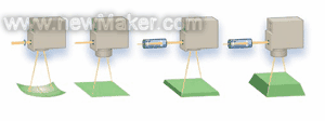
Figure 3: Focusing of the laser beam through the scanning system (from left): Pre-focusing lens, F-Theta lens, dynamic pre-focusing, and dynamic pre-focusing in combination with F-Theta lens.
The diameter of the focal spot is determined by the focal length of the lens f, the surface area that can be treated, and the type of laser and aperture of the scanning head. For a Gaussian beam, its focal spot diameter s can be calculated by the following formula:
s = λf M2 k / d
Here, λ is the laser wavelength, M2 represents the beam quality, and d is the beam diameter before passing through the focusing optics. The parameter k characterizes the diffraction effect of the laser beam due to the aperture or within the lens. In order to maximize the power density at the focal point, ie, to increase the processing speed, the beam width must be extended to be equal to the scanhead aperture. In this case, k = 1.83.
In some applications, a fast-moving lens system is placed at the front of the scanner to adjust the focal length to match the distance between the deflection mirror and the target point of the laser on the workpiece. This varioSCAN variable scanning optics is particularly useful when no suitable F-Theta lens is available, such as when the beam diameter is long or the image field is large, it can be used at high laser power or laser wavelengths. In addition, these varioSCAN variable scanning optics allow 3D machining within the scanning range. They can be used individually or with F-Theta lenses.
Figure 4: Friendly Graphical User Interface (GUI) Software (LaserWare, Inc., Alase Technologies, Inc., USA)
Provides an interface between the user and the scanning device controller.
The DSP control panel with memory functions as an application software, hardware interface between the scanner head and the laser. These panels synchronize the laser control and scanner movements and the completion of the image correction to ensure that the text is accurately positioned without pincushion distortion and at the same time ensure constant marking process speed.
For the micromachining of materials, special scanning heads with very precise dynamics can be used to quickly cool the motor and/or electronics to minimize long-term drift. Scanning heads with an aperture of 14 mm can be equipped with additional high precision position detectors for automatic calibration.
Figure 5: The all-digital intelliSCAN 10 used to meet the high demands of the application.
Technological innovation
New materials, the emergence of new laser sources and advances in production processes will bring about powerful developments in scanning systems for material processing.
Its further advantage lies in being able to monitor the status parameters of the scanning system through software, which provides new possibilities for the use in areas such as remote diagnosis and customer support. The scanner's position and speed parameters can be digitally queried and used during later processing.
Source: Jiagong Machine Grid
Sealing Machine,Dbf Sealing Machine,Sealing Machine with Ink Printing
Shanghai Packaging Machinery Co., Ltd. , http://www.zjvacuumsealer.com