In today's engineering world, professionals face increasingly complex and demanding testing scenarios. While a device may perform perfectly in the lab, it can encounter unexpected issues during real-world deployment, leading to operational failures. These problems can cause customer dissatisfaction, production losses, costly repairs, and even safety risks. When such issues arise, customers expect field engineers to quickly and accurately identify and resolve the faults, ensuring minimal downtime. This places significant pressure on fault diagnosis engineers, who must solve problems efficiently under challenging conditions.
On-site troubleshooting often requires engineers to carry compact yet powerful tools that can capture waveform anomalies—such as timing errors, crosstalk, transients, or power quality issues. These tools are essential for functional testing, fault localization, and error tracking. The PicoScope oscilloscope is an ideal solution. It’s small enough to fit in a shirt pocket or laptop bag, yet its performance rivals or exceeds many traditional laboratory instruments. This makes it a valuable asset for engineers tackling real-world challenges with speed and precision.
This article explores common troubleshooting scenarios and demonstrates how the PicoScope 2200A and 5000 Series oscilloscopes can help identify waveform irregularities to diagnose and resolve issues effectively.
During the design phase, engineers rely on a comprehensive set of tools to ensure product reliability. These include simulation software, oscilloscopes, signal generators, logic analyzers, and more. Collaboration between teams is also crucial. For instance, if an FPGA engineer encounters a memory interface issue, they can consult with hardware specialists to troubleshoot and resolve the problem.
However, once a product is deployed in the field, the situation changes drastically. Customers become frustrated when products fail, especially if they’re used in critical applications like manufacturing or healthcare. Time becomes a key factor, as delays can lead to significant financial losses or even life-threatening situations. Engineers often have to travel to remote locations without access to their usual lab equipment, making it difficult to diagnose and fix issues quickly.
In such cases, a portable, high-performance tool like the PicoScope becomes indispensable. It not only offers the functionality of traditional lab instruments but also allows engineers to share field data with their teams for collaborative analysis. This ensures that problems are identified and resolved efficiently, regardless of location.
The PicoScope USB oscilloscope is a compact, powerful instrument that replaces bulky benchtop models. It supports 2 or 4 channels, up to 500MHz bandwidth, and includes features like advanced triggering, serial decoding, mask testing, and waveform math. With up to 2GB of memory depth, it enables real-time analysis of complex systems. Additionally, the free PicoScope software allows for offline or remote data analysis, enhancing team collaboration.
This article will demonstrate how to use the 2-channel PicoScope 2204A and 4-channel PicoScope 5000 Series to troubleshoot various issues.
One of the first steps in identifying design flaws is basic signal integrity and timing analysis. Engineers need to verify whether clock signals are stable, logic edges meet specifications, and if there’s any noise or crosstalk affecting the circuit. They also check if the device performs reliably under varying environmental conditions.
Figure 1 shows an I2C clock and data waveform captured using the PicoScope 2200A. The four panels display different scales of the same waveform, helping users focus on specific areas of interest.
Another important task is detecting glitches. Engineers can set up triggers for pulse width, distortion, or logic states. Figure 2 illustrates how to configure a digital error trigger. Alternatively, a mask test can be used to detect waveform deviations over time. If the signal falls outside the defined mask, the PicoScope triggers an alarm, saving the faulty waveform for further analysis.
Figure 3 highlights the mask test feature, which works in both time and frequency domains. It can detect interference from switching power supplies and trigger alarms accordingly.
When debugging a system, engineers often analyze program execution to ensure data is correctly written or read. Figure 4 shows I2C bus decoding, where a glitch on the clock or data line is clearly visible. The PicoScope 5000 Series can store thousands of packets, allowing detailed tracking of program behavior and quick identification of errors.
Power analysis is another critical aspect. Issues like voltage dips, spikes, or harmonic distortions can affect device performance. Figure 5 displays the voltage and current waveforms of a laptop power supply, along with the calculated power in kW. This helps engineers evaluate the impact of non-linear loads on the system.
Signal integrity and edge detection are also important. Engineers may simulate abnormal signals using the built-in arbitrary waveform generator (AWG) to test device responses. Figure 6 shows how a serial data stream with added glitches can be captured and re-output, simulating worst-case scenarios to validate system robustness.
Finally, teamwork plays a vital role in successful troubleshooting. Engineers can share data via screenshots or CSV files, and the PicoScope software supports seamless collaboration across teams. This allows for faster problem resolution and improved product reliability.
In conclusion, the PicoScope is a versatile, portable tool that empowers engineers to tackle real-world challenges with confidence and efficiency. Whether in the lab or the field, it provides the performance and flexibility needed to diagnose and resolve complex issues quickly.
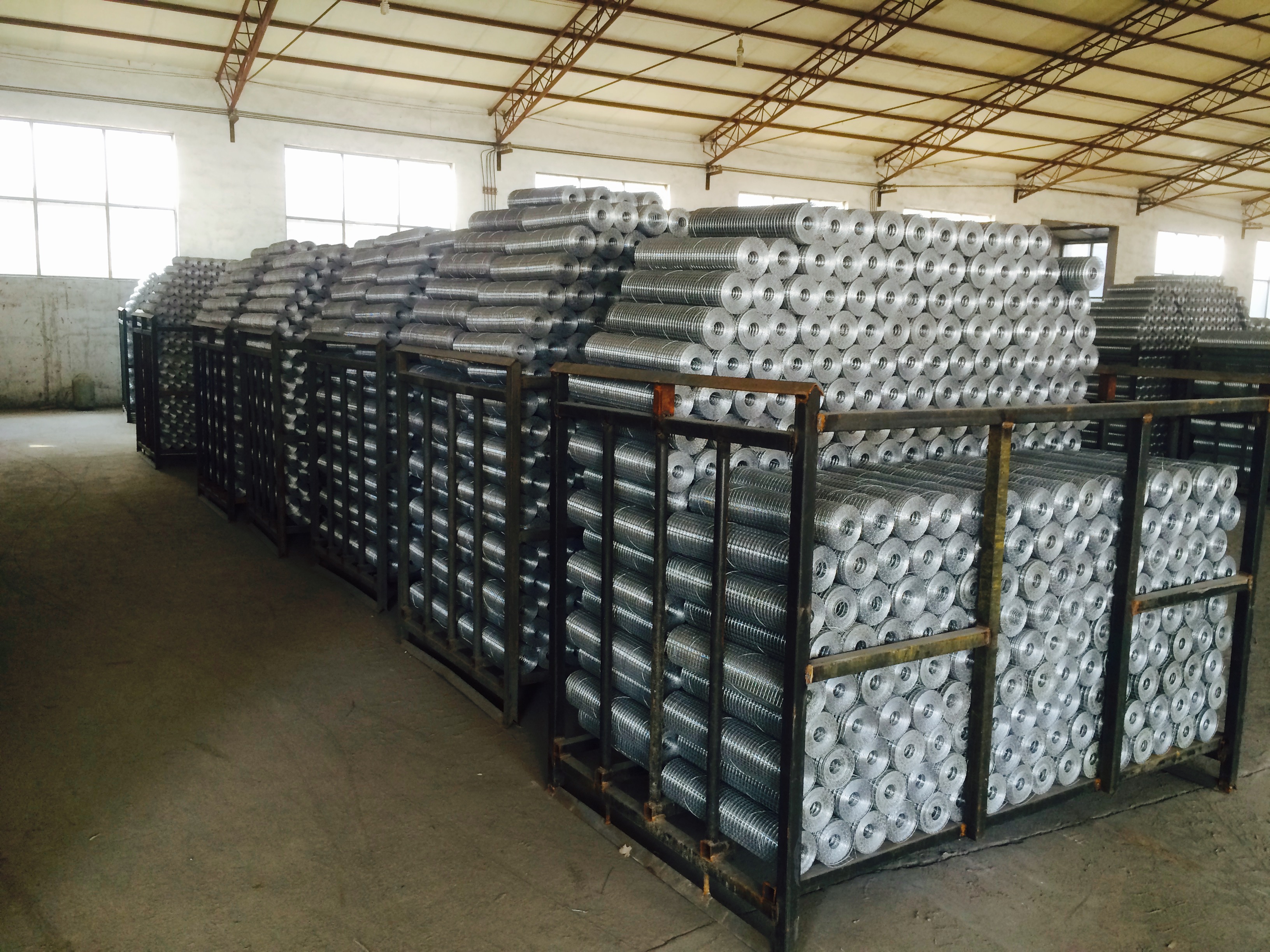
Welded Wire Mesh
Welded wire mesh, also named hardware cloth in USA, is an electric
fusion welded prefabricated joined grid consisting of a series of parallel
longitudinal Wires with accurate spacing welded to cross wires at the required
spacing. It is widely used for screens
and partitions, yard and garden fence, barriers and cages for animal, tree and shrub protection.
Features
Materials:
Low carbon steel wire.
Surface
Treatment:Hot
dipped/Electro galvanized after (or before)welded; Galvanized core + Plastic
coated.
Benefits
Ÿ Extremely
strong and durable
Ÿ Attractive
- non-intrusive to landscape
Ÿ Easy
to clean when used in animal cages
Ÿ Weather
proof - rust and corrosion resistant
Ÿ Toughest,
longest lasting wire mesh available
Ÿ
Stainless Steel Welded Wire Mesh, Hardware Cloth, Galvanized Wire Mesh, Hot Dipped Galvanized Welded Wire Mesh, GAW Welded Wire Mesh
DINGZHOU TIAN YILONG METAL PRODUCTS CO., LTD. , https://www.wiremeshsolution.com
